1Introduction
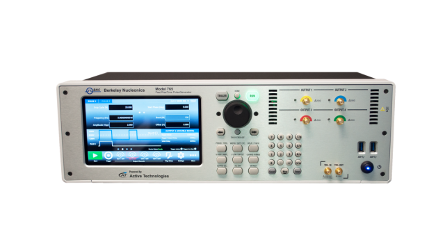
The Model 765 Pulse Generator is a feature-rich pulse and delay generator with 2 or 4 channels of completely programmable pulse and delay generation. The instrument offers many improvements over our previous design: faster transition times, narrow pulses, broader and more accurate amplitude control, and a redesigned user interface. Take control of your time and amplitude domain.
Intuitive User Interface
The front panel controls for the Model 765 Pulse Generator include a 7" touchscreen and tactile controls for most operations. The touchscreen was designed to drive simplicity in operating and programming by giving users smartphone-like architecture complete with gesture control. The primary channel controls and programming options are easy to navigate, with a swipe gesture to move from channel to channel. Handy features like combining multiple pulses on one output can be graphically controlled and are easily identified on the screen. In addition, a rotary encoder and backlit pushbuttons provide an alternative yet familiar experience to users needing front panel controls.
Rotary Encoder: The Model 765 front panel encoder is ideal for fine tuning pulse parameters on the fly. Dialing the encoder will change the value in continuous, analog fashion. Pushing the encoder in will move the value adjustment from fine to coarse adjust, further simplifying setup and on-the-fly adjustments.
Fast Rise Times and Plenty of Range
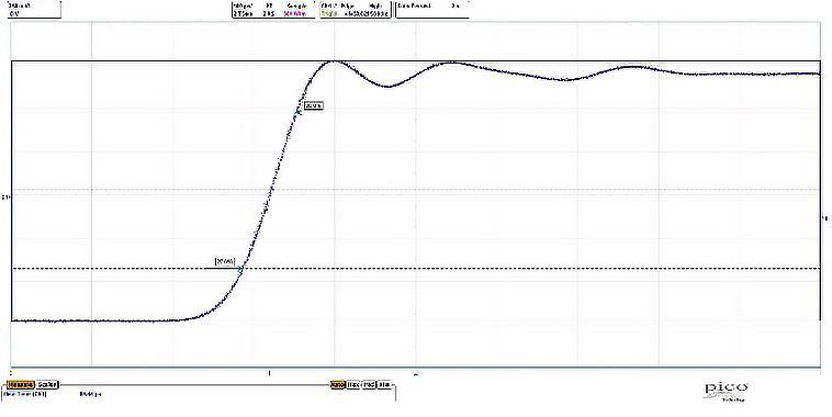
The Model 765 offers 70 ps rise and fall times (@ 5.0 V pk-pk) over a large time domain. Our front end electronics circuit and new analog edge converter have been integrated into the pulse generator using a proprietary technology that virtually eliminates overshoot (< 5.0% typical) and ringing.
Programming
The Model 765 offers several useful remote programming options. In addition, the networking feature allows users to use a VXI-11 LAN protocol to network the instrument for printing, file sharing, internet access, and remote login. The remote programming uses common SCPI commands, ensuring compatibility with a wide range of development environments. Visual Studio, .NET, LabView, LabWindows/CVI, Microsoft Visual Studio, and MatLab are all supported. Berkeley Nucleonics provides a comprehensive Software Development Kit (SDK) at no additional charge.
Applications
- Big physics
- Collider experiments
- Laser modulation
- Radar and sonar systems
- Semiconductor test
2Inputs & Outputs
Pulse Out: The Model 765 offers inputs and outputs on the front and rear panel to accommodate users with rackmount or benchtop applications. The Pulse Out connectors are DC-coupled SMA connectors with 50 Ohm impedance and strain-relief panel mounts. The pulse out settings can be independently positive or negative (0 V to +/-5 V, adjustable). The following table shows the parameter limits for pulse outputs:
| Parameter | Min | Max |
|---|---|---|
| Voltage | -5.0 V | +5.0 V |
| Amplitude | 10 mVpp | 5 Vpp |
| Offset | -2.5 V | +2.5 V |
| Width | 300 ps | 8 sec |
| Duty Cycle | < 1% | > 99% |
| Period | 5 ns | 8 sec |
| Frequency | 0.125 Hz | 200 MHz |
| Delay | 0 sec | 8 sec |
| Burst N | 1 | 4,294,967,295 |
Table 1: Pulse Out Limits
Trigger In / Out: The Model 765 Trigger Input is an SMA connector with a programmable impedance and threshold (50 Ohm / 1k Ohm, -10.0 V to +10.0 V). The programmable trigger threshold has a resolution of 4 mV, ensuring precise triggering. The Model 765 can trigger on signals down to 50 mV and as narrow as 1 ns, and a convenient Autosense function will measure the current trigger input level. The Model 765 also measures the Trigger In frequency and displays the result in the Trigger Setup Window. The Trigger Out is an SMA connector with 50 Ohm impedance and an output voltage range of 1.8 V to 3.3 V (adjustable).
USB: There are 2 handy USB 3.0 ports on the front panel for auxiliary equipment such as a keyboard, additional storage, or other system requirements.
Rear Panel: Additional input and output connectors on the rear panel include PS/2 mouse and keyboard connectors, external monitor ports (HDMI, VGA), LAN, and Audio.
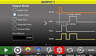
Multi-pulse Mode: The Model 765 allows users to combine four digitally programmed pulses on each output. This allows complex timing sequences and repetition rates to 800 MHz. The graphical user interface allows users an easy representation of the outputs on a given channel. Below is a simple example showing different delay and width settings from a common trigger.
3Application Ideas
Semiconductor Test
Characterization of non-volatile memory cells requires very precise pulse control, both in amplitude and time domains. The Model 765, with 10 ps time resolution and 10 mV amplitude resolution, allows just that. R&D in memory devices is leading to cell types which have the speed of RAM and the data retention of mass memory. Emerging R&D exists also in FeRAM (Ferroelectric RAM), ReRAM (Resistive RAM), MRAM (Magnetoresistive RAM), STT-MRAM (Spin-Transfer Torque Magnetoresistive RAM), and PCM (Phase Change Memory). This R&D is based on changing the conductivity of a material using different stimuli principles. Examples include formation and destruction of a thin wire into a material stack, changing the material structure from amorphous to polycrystalline, alignment of magnetic fields, and similar approaches. Accurate front-end control in all these processes is critical for successful results.
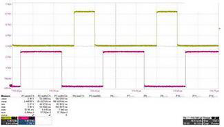
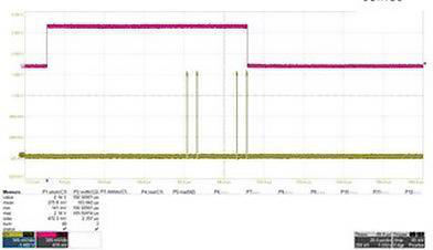
MRAM memory cells use Magnetic Tunnel Junctions (MTJ) that consist of two ferromagnets separated by a thin insulator. If the magnetic fields of the two ferromagnets are oriented in the same direction, electrons can tunnel from one ferromagnet to the other through the insulator. The first ferromagnet has a fixed magnetic field and the second can be changed by applying a current pulse. Inverting the magnetic field orientation changes the conductivity of the stack. To program or erase a bit, a current pulse is applied through the stack. The efficiency of the program/erase process depends on the duration and amplitude of the pulse, so R&D engineers are testing different combinations of pulse widths and amplitudes (and repetition rates). In the scope trace below, the 50 ns pulse @ 3.3 V is used to erase a single cell and the 100 ns pulse @ 3.3 V is used to erase an array of cells.
Radar
In radar testing, many situations make actual target measurements impractical. Simulating moving targets is a solution for expediting the R&D, calibration, and test of radar systems. The typical radar system measures the time of flight of the signal and calculates the distance from the target using the following equation: Distance (km) = (DelayTime (sec) / 2) × 3×105 km/s, where 3×10⁵ km/s is an approximation of the speed of light.
The delay between transmitted and received signals is dependent on distance. In complex systems, multiple targets are detected and the radar system is required to distinguish between various targets. A multi-channel pulse generator is used to test the detection ability of the radar without requiring actual field measurements of moving targets. The Model 765 is capable of multiple pulses per pulse period, allowing up to 4 pulses with different widths and delays to be generated on a single output. A repetition rate of 200 MHz allows testing the real time frequency capabilities of the radar system. With resolution of 10 ps and jitter < 10 ps RMS, the pulse generator can verify and calibrate a radar system with resolution under 1 centimeter. Shown below is an example of Quad-Pulse mode, 4 different narrow pulses with unique delays from the Trigger In, simulating the detection of multiple targets.
4Ordering Information
| Model / Part No. | Description |
|---|---|
| Model 765-2C | 2 Channel Pulse Generator |
| Model 765-4C | 4 Channel Pulse Generator |
| P/N 765-RMKit | 19" Rack Mount Kit for the 765-X |
| P/N 765-SSKit | 1 TB Solid State Storage Drive for 765-X |
For a configured quote, contact Berkeley Nucleonics Corporation · info@berkeleynucleonics.com · 415-453-9955.
5Specifications — Timing
Pulse Period
| Parameter | Specification |
|---|---|
| Range (spec.) | 5 ns to 8 sec |
| Resolution (spec.) | 10 ps |
| RMS Jitter1 (Integration Range 100 Hz to 10 MHz, Fout = 200 MHz) | 4 ps |
Pulse Frequency
| Parameter | Specification |
|---|---|
| Range (spec.) | 0.125 Hz to 200 MHz (single pulse mode) |
| 0.25 Hz to 400 MHz (double pulse mode) | |
| 0.375 Hz to 600 MHz (triple pulse mode) | |
| 0.5 Hz to 800 MHz (quadruple pulse mode) | |
| Accuracy | ± 2 ppm max |
Pulse Width
| Parameter | Specification |
|---|---|
| Range (spec.)2 | 300 ps to (period − 300 ps) |
| Resolution (spec.) | 10 ps |
| Accuracy | ± (0.1% + 30 ps) |
| RMS Jitter1 | < 10 ps |
Pulse Delay (single / double / triple / quadruple)
| Parameter | Specification |
|---|---|
| Range (spec.) | 0 ps to period |
| Resolution (spec.) | 10 ps |
| Accuracy | ± (0.1% + 100 ps) |
6Specifications — Output (50 Ohm load)
| Parameter | Specification |
|---|---|
| Impedance | 50 Ohm nominal |
| Amplitude — Range pk-pk (spec.) | 10 mVpp to 5 Vpp |
| Amplitude — Resolution (spec.) | 4 mV (250 mVpp to 5 Vpp), 1 mV (10 mVpp to 250 mVpp) |
| Amplitude — Absolute accuracy (spec.) | ± (1% of amplitude p-p + 1% of |DC Offset| + 20 mV) |
| DC Offset (HV only) — Range (spec.) | 0 V or ± 25 V adjustable |
| DC Offset (HV only) — Resolution (spec.) | 10 mV |
| Baseline Offset — Range (spec.) | ± 2.5 V adjustable |
| Baseline Offset — Resolution (spec.) | 2 mV |
| Rise/Fall Time (20% to 80%) | < 70 ps |
| Rise/Fall Time (10% to 90%) | < 95 ps (1 Vpp amplitude), < 105 ps (5 Vpp amplitude) |
| Overshoot | < 5% |
| Channel to Channel RMS Jitter1 | < 10 ps |
| Initial Delay | 0 s to 8 s (retriggerable delay off); 0 s to 2.5 us (retriggerable delay on) |
1 All channels at the same frequency in Single Pulse mode and Continuous mode.
2 With Offset ≠ 0 V the width can deviate from this specification depending on the Offset voltage and other parameters.
7Specifications — Trigger
Trigger Input
| Parameter | Specification |
|---|---|
| Impedance | 50 Ohm or 1k Ohm programmable |
| Range (spec.) | ± 3.5 V (50 Ohm input impedance) |
| ± 10 V (1k Ohm input impedance) | |
| Minimum detectable amplitude (spec.) | < 50 mVpp |
| Threshold — Range (spec.) | ± 8 V |
| Threshold — Resolution (spec.) | 10 mV |
| Threshold — Accuracy | ± 100 mV |
| Max. input frequency (spec.) | 40 MHz |
| Min. pulse width (spec.) | 1 ns |
| Max. external width mode input frequency (spec.) | 1 GHz |
| Edge selection | Positive, negative, both |
| Prescaler (for every channel) | 0 to 65535 |
Trigger Output
| Parameter | Specification |
|---|---|
| Impedance | 50 Ohm nominal |
| Amplitude (open load) — Range (spec.) | 1.8 V to 3.3 V adjustable |
| Amplitude (open load) — Resolution (spec.) | 1 mV |
| Amplitude (open load) — Accuracy | ± 1% |
| Delay (trigger in to trigger out) | < 100 ns |
| RMS jitter (trigger in to trigger out) | < 30 ps (Trigger IN frequency ≤ 15 MHz) |
| Width | 10 ns (single, burst mode); Period/2 (continuous mode) |
| Initial delay | 0 s to 8 s (continuous mode); 0 s to 2.5 us (single, burst, gated mode) |
Internal Timer
| Parameter | Specification |
|---|---|
| Time range (frequency range) | 25 ns to 42.9 sec (40 MHz to 23.3 mHz) |
| Time resolution | 1 ps |
| Frequency accuracy | ± 2 ppm max |
External Clock IN
| Parameter | Specification |
|---|---|
| Connector type | SMA on rear panel |
| Input impedance | 50 Ω, AC coupled |
| Input voltage range | -5 dBm to 4 dBm sine or square wave (rise time T10-90 < 1 ns and duty cycle from 40% to 60%) |
| Damage level | +8 dBm or ± 15 VDC max |
| Frequency range | 10 MHz to 100 MHz |
External Clock OUT
| Parameter | Specification |
|---|---|
| Connector type | SMA on rear panel |
| Output impedance | 50 Ω, DC coupled |
| Frequency | 10 MHz or External Clock IN frequency |
| Accuracy | ± 2 ppm max |
| Aging | ± 1.0 ppm/year max |
| Amplitude | Square wave: 0 V to 1.25 V into 50 Ω, 0 V to 2.5 V into High Z |
8Specifications — Programmability, Power & Environmental
Programmability
| Parameter | Specification |
|---|---|
| Trigger modes | Single, continuous, burst, gated |
| Multiple pulse modes | Single, double, triple, quadruple, external width |
Power
| Parameter | Specification |
|---|---|
| Voltage range | 100-240 VAC ± 10% |
| Frequency range | 47-63 Hz |
| Max. power consumption | 120 W |
Environmental Characteristics
| Parameter | Specification |
|---|---|
| Temperature (operating) | +5 °C to +40 °C (+41 °F to 104 °F) |
| Temperature (non-operating) | -20 °C to +60 °C (-4 °F to 140 °F) |
| Humidity (operating) | 5% to 80% relative humidity with a maximum wet bulb temperature of 29 °C at or below +40 °C (upper limit de-rates to 20.6% relative humidity at +40 °C). Non-condensing. |
| Humidity (non-operating) | 5% to 95% relative humidity with a maximum wet bulb temperature of 40 °C at or below +60 °C (upper limit de-rates to 29.8% relative humidity at +60 °C). Non-condensing. |
| Altitude (operating) | 3,000 meters (9,842 feet) maximum at or below 25° |
| Altitude (non-operating) | 12,000 meters (39,370 feet) maximum |
EMC and Safety
| Parameter | Specification |
|---|---|
| Safety | EN61010-1 |
| Main Standards | EN 61326-1:2013 — Electrical equipment for measurement, control and laboratory use — EMC requirements — Part 1: General requirements |
| Immunity | EN 61326-1:2013 |
9General Characteristics
| Characteristic | Specification |
|---|---|
| Display | 7 inch, 1024x600, capacitive touch LCD |
| Operating system | Windows 10 |
| External dimensions | W 445 mm × H 135 mm × D 320 mm (3U 19" rackmount) |
| Weight | 21.4 lbs (9.7 kg) |
| Front panel connectors | All Output (SMA), TRG.IN (SMA), TRG.OUT (SMA), 2 USB 3.0 ports |
| Rear panel connectors | External Monitor ports (HDMI, VGA); 2 USB 2.0 ports; 2 USB 3.0 ports; 3 COM ports; 2 Ethernet ports (10/100/1000BaseT Ethernet, RJ45 port); Audio In/Out ports; 2 PS/2 keyboard and mouse ports; External Clock IN (SMA); External Clock OUT (SMA) |
| Hard disk | 128 GB SSD |
| Processor | Intel® Celeron J1900, 2 GHz (or better) |
| Processor memory | 8 GB |