1Overview
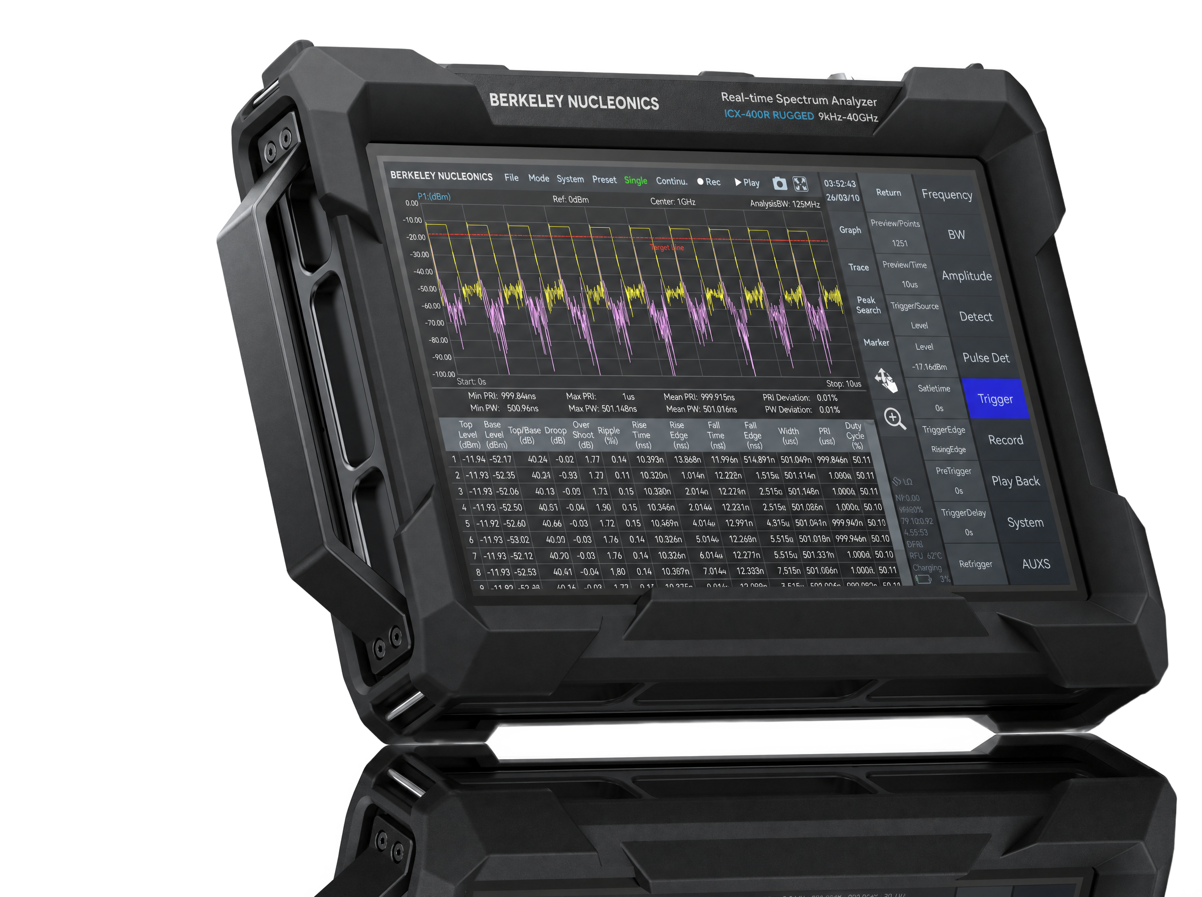
The Berkeley Nucleonics ICX-FieldHawk Rugged is a real-time spectrum analyzer built for solid RF performance in the field, on the flight line, and inside automated test racks. The series covers 9 kHz up to 9.5, 20, or 40 GHz with a standard analysis bandwidth of 100 MHz. A fast FFT design pushes sweep speed past 1 THz/s.
The rugged housing wraps the same measurement engine as the handheld ICX-FieldHawk in an impact-protected chassis with corner bumpers, so it holds spectral purity through the shock, vibration, and wide temperature swings of field and vehicle use. Extended temperature classes reach down to -40 °C for cold-environment deployment.
Every unit ships with the standard SpecICX-gen3 measurement suite: channel power, OBW, X dB bandwidth, harmonic measurement, SEM, AM/FM demodulation, and automatic phase noise analysis, plus spectrum, spectrogram, and historical trace views.
Highly compatible API interfaces support mainstream programming languages including C/C++, C#, Python, MATLAB, Qt, and LabVIEW on Windows and Linux. That makes secondary development straightforward and integration into larger systems clean. Talk to a Berkeley Nucleonics engineer about matching the right model to your application.
2Key Features
- Rugged, field-ready chassis. Impact-protected housing with corner bumpers for vehicle, flight-line, and outdoor use without trading away RF measurement depth.
- Wide operating temperature. Standard 0 to 50 °C, with optional T1 (-20 to +65 °C) and T2 (-40 to +65 °C) temperature classes.
- Frequency range 9 kHz to 9.5 / 20 / 40 GHz across the ICX-090, ICX-200, and ICX-400 models.
- 100 MHz analysis bandwidth with gapless, overlap-free real-time FFT.
- 1 GHz DANL below -160 dBm/Hz for low-level signal work.
- 1 GHz phase noise below -100 dBc/Hz at 10 kHz offset.
- Unified API and SCPI. C/C++, C#, Python, MATLAB, Qt, and LabVIEW on Windows and Linux, with standard SCPI remote control.
- Built for automated test. Integrates cleanly into ATE racks and unattended monitoring systems.
3Models & Frequency Range
Three models share the same rugged platform and 100 MHz analysis bandwidth. They differ in upper frequency limit. Pick the band that covers your highest signal of interest.
| Model | Frequency range | Analysis bandwidth |
|---|---|---|
| ICX-090 | 9 kHz to 9.5 GHz | 100 MHz |
| ICX-200 | 9 kHz to 20 GHz | 100 MHz |
| ICX-400 | 9 kHz to 40 GHz | 100 MHz |
4Operating Modes
The ICX-FieldHawk offers main operating modes including Standard Spectrum Analysis, IQ Streaming, Power Detection, Real-Time Spectrum, Phase Noise Measurement, and Harmonics Analysis. Digital Demodulation is available as an option.
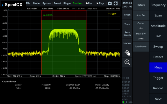
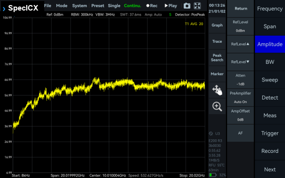
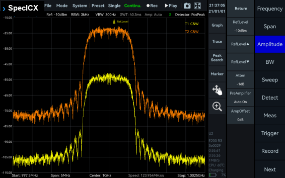
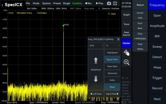
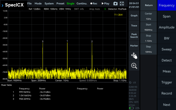
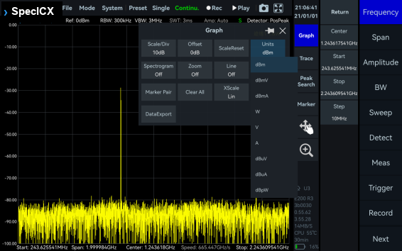
Standard Spectrum Analysis
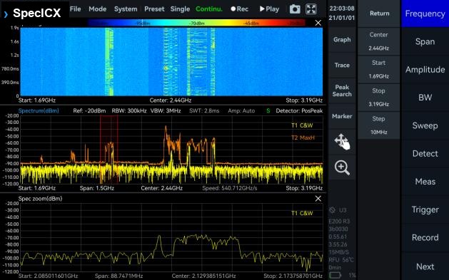
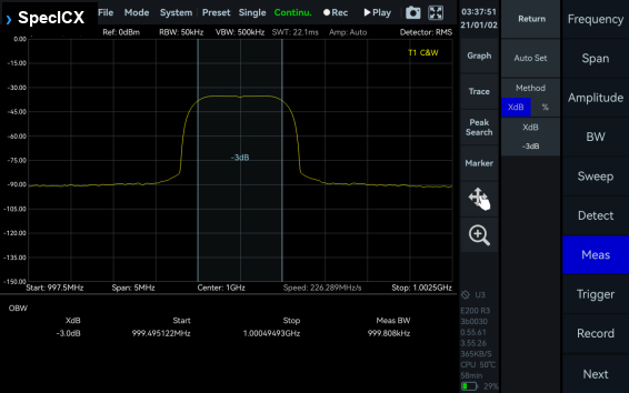
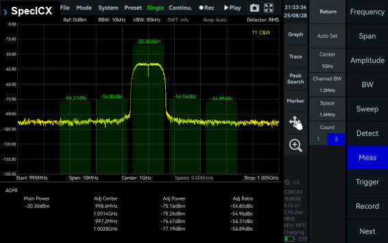
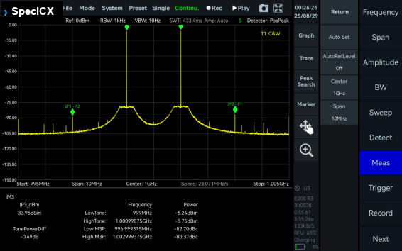
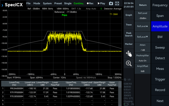
This mode provides a wide range of measurement functions, including full-span spectrum sweep, channel power, OBW, ACPR, IM3, and SEM. It also supports spectrum recording and playback. Combined with auxiliary tools such as signal tracking, peak table, and amplitude correction, it delivers a one-stop platform for comprehensive spectrum check.
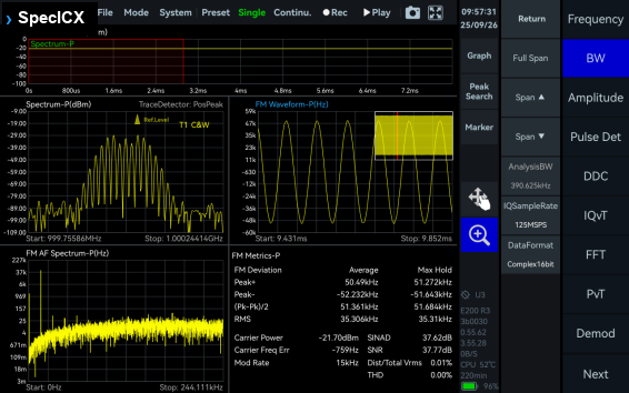
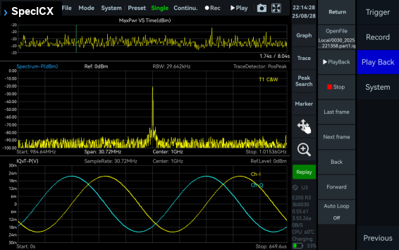
IQ Streaming Analysis
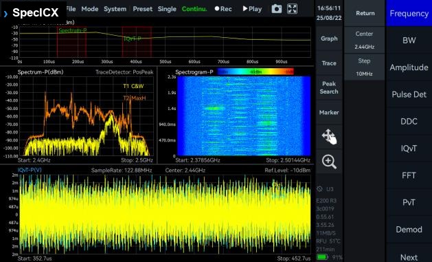
This mode supports up to 100 MHz analysis bandwidth and allows IQ data acquisition through multiple trigger methods. It provides IQ time-domain waveform display, spectrum and spectrogram views, AM/FM demodulation, and digital down-conversion (DDC).
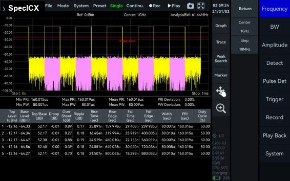
Power Detection Analysis
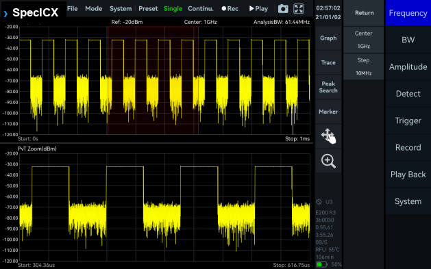
This mode enables detection and analysis of time-domain signals within the analysis bandwidth. It suits applications focused on in-band power-versus-time relationships, such as pulse signal measurements.
Real-Time Spectrum Analysis
This mode is powered by a high-speed FPGA-based FFT engine. With strictly gapless and overlap-free FFT, it achieves true real-time monitoring across the full bandwidth.

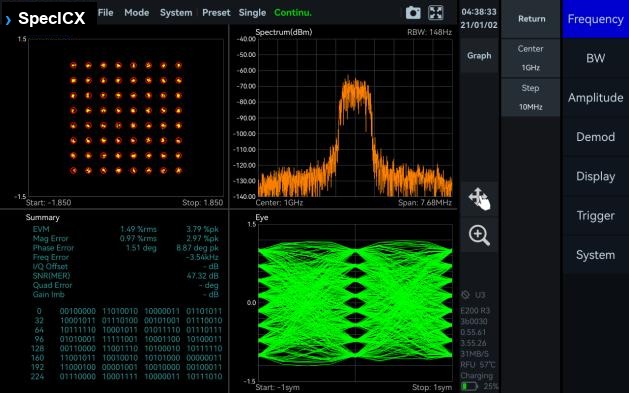
Digital Demodulation (option)
This mode supports 2ASK, 2FSK, 4FSK, GMSK, BPSK, QPSK, 8PSK, 16QAM, 64QAM, 128QAM, and 256QAM signals.
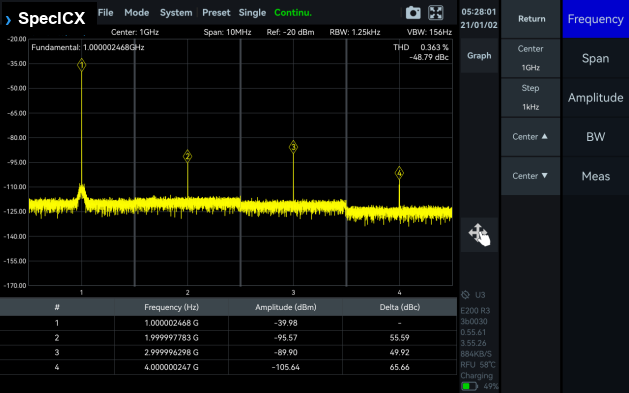
Harmonics Analysis
This mode supports detection and measurement of up to 10 harmonic components, including harmonic peaks, harmonic channel power, and total harmonic distortion.
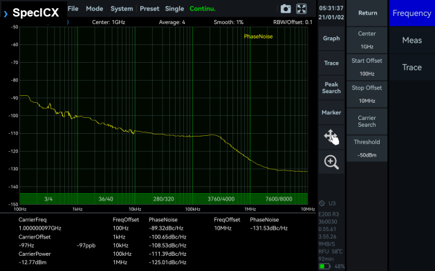
Phase Noise Measurement
This mode supports offset ranges from 1 Hz to 10 MHz for evaluating carrier phase stability. With the built-in automatic carrier search function, the software can quickly locate the target carrier without manual adjustment.
5Main Functions
A standard set of measurement and utility functions runs on every ICX-FieldHawk. Pulse Detection and digital demodulation are software options.

6Frequency & Spectrum Purity
Frequency
| Parameter | Specification |
|---|---|
| Reference clock | Internal or external |
| Frequency accuracy, TCXO (std.) | <1 ppm, manual correction is available |
| Frequency accuracy, OCXO (opt01) | <1 ppm, manual correction is available |
| Aging and temperature stability, TCXO (std.) | <1 ppm/year, <1 ppm |
| Aging and temperature stability, OCXO (opt01) | <1 ppm/year, <0.15 ppm |
SSB Phase Noise (dBc/Hz)
| Offset frequency | ICX-090 | ICX-200 | ICX-400 | |||
|---|---|---|---|---|---|---|
| 1 GHz | 9.5 GHz | 1 GHz | 20 GHz | 1 GHz | 40 GHz | |
| 1 kHz | -95.2 | -91.5 | -91.2 | -80.6 | -99.0 | -78.4 |
| 10 kHz | -101.6 | -98.5 | -99.7 | -90.6 | -107.5 | -85.7 |
| 100 kHz | -100.6 | -99.7 | -101.1 | -96.2 | -107.7 | -85.1 |
| 1 MHz | -120.9 | -116.2 | -121.6 | -111.5 | -122.7 | -100.8 |
Residual Response (dBm)
Spur reject = bypass, RBW = 1 kHz, PosPeak detector.
| Reference level (R.L.) | ICX-090 | ICX-200 | ICX-400 | |||
|---|---|---|---|---|---|---|
| 0 dBm | -50 dBm | 0 dBm | -50 dBm | 0 dBm | -50 dBm | |
| 9 kHz to 1 GHz | -83 | -120 | -90 | -120 | -72 | -103 |
| 1 GHz to 3 GHz | -83 | -120 | -90 | -120 | -72 | -103 |
| 3 GHz to 10 GHz | -90 | -130 | -90 | -120 | -72 | -103 |
| 10 GHz to 20 GHz | - | - | -90 | -120 | -91 | -115 |
| 20 GHz to 40 GHz | - | - | - | - | -85 | -103 |
IF Rejection (dBc), Typical
| Spur reject function | ICX-090 | ICX-200 | ICX-400 | |||
|---|---|---|---|---|---|---|
| enhanced | bypass | enhanced | bypass | enhanced | bypass | |
| 9 kHz to 40 GHz | >90 | >80 | >90 | >80 | 8.2 to 21.75 GHz >68; other bands >90 | - |
Image Rejection (dBc), Typical
| Spur reject function | ICX-090 | ICX-200 | ICX-400 | |||
|---|---|---|---|---|---|---|
| standard | bypass | standard | bypass | standard | bypass | |
| 90 MHz to 3 GHz | >90 | >76 | >90 | >79 | >90 | - |
| 3 GHz to 9.5 GHz | >90 | >60 | >90 | >68 | >90 | - |
| 9.5 GHz to 20 GHz | - | - | >90 | >60 | >90 | - |
| 20 GHz to 33 GHz | - | - | - | - | >90 | - |
| 33 GHz to 40 GHz | - | - | - | - | >58 | - |
Local Oscillator Related Spurious
| Parameter | Specification |
|---|---|
| Local oscillator related spurious | <-65 dBc, center frequency ± (N/M) × 125 MHz, N, M = 1, 2, 3, 4, 5... |
IIP3 / IIP2 (dBm)
Each cell lists IIP3 / IIP2.
| Carrier frequency | ICX-090 | ICX-200 | ICX-400 | |||
|---|---|---|---|---|---|---|
| 1 GHz | 9.5 GHz | 1 GHz | 20 GHz | 1 GHz | 40 GHz | |
| R.L. = 20 dBm | 46.1 / 83.2 | 40.5 / 92.8 | 45.5 / 82.6 | 35.3 / 93.6 | 40.3 / 75.5 | 31.7 / 88.6 |
| R.L. = 0 dBm | 26.7 / 85.0 | 19.2 / 90.3 | 25.5 / 81.1 | 21.0 / 89.0 | 27.4 / 45.3 | 10.3 / 86.1 |
| R.L. = -20 dBm | 10.5 / 82.2 | 2.0 / 49.3 | 7.9 / 81.5 | -4.5 / 55.3 | 8.7 / 25.2 | 4.8 / 66.6 |
7Amplitude & DANL
Amplitude
| Parameter | ICX-090 / ICX-200 | ICX-400 |
|---|---|---|
| Display range | DANL to 23 dBm (typ.) | DANL to 20 dBm (typ.) |
| Reference level (R.L.) | -50 dBm to +23 dBm (typ.) | -50 dBm to +20 dBm (typ.) |
| VSWR | 90 MHz to 9.5/20 GHz: <2.0:1 | 90 MHz to 16 GHz: <2.0:1; 16 GHz to 40 GHz: <3.0:1 |
| Max. DC voltage | ±10 VDC | |
| IF in-band flatness | ±2.0 dB | |
| Max. input power (CW) | 23 dBm: 50 MHz to 9.5/20/40 GHz and the preamplifier is off; 10 dBm: 9 kHz to 50 MHz or preamplifier is on | |
| Amplitude accuracy | 9 kHz to 9.5 GHz: ±2.0 dB; 9.5 GHz to 20/40 GHz: ±3.0 dB | |
| RF preamplifiers | Automatically turn on or forcibly turn off | |
Display Average Noise Level (DANL, dBm/Hz)
RBW = 1 kHz.
| Reference level (R.L.) | ICX-090 | ICX-200 | ICX-400 | |||
|---|---|---|---|---|---|---|
| -20 dBm | -50 dBm | -20 dBm | -50 dBm | -20 dBm | -50 dBm | |
| 9 kHz to 1 MHz | -143.0 | -152.4 | -143.6 | -152.6 | -136.0 | -145.8 |
| 1 MHz to 90 MHz | -152.0 | -159.2 | -151.8 | -160.0 | -153.7 | -158.0 |
| 90 MHz to 3 GHz | -146.0 | -167.5 | -149.7 | -166.3 | -154.1 | -159.9 |
| 3 GHz to 9.5 GHz | -153.6 | -167.0 | -151.4 | -157.5 | -154.1 | -159.9 |
| 9.5 GHz to 19 GHz | - | - | -156.1 | -160.6 | -156.8 | -161.5 |
| 19 GHz to 20 GHz | - | - | -156.1 | -160.6 | -145.2 | -149.3 |
| 20 GHz to 40 GHz | - | - | - | - | -145.2 | -149.3 |
8Sweep, Detection & Real-Time Analysis
Standard Spectrum Analysis
| Parameter | Specification |
|---|---|
| Detector | PosPeak, NegPeak, Sample, Average, RMS, MaxPower |
| RBW | 1 Hz to 10 MHz |
| VBW | 1 Hz to 10 MHz |
| Data chart | SpecICX-gen3 software provides spectrum, spectrogram, and historical trace |
| Measurements | Channel power, OBW, X dB bandwidth, Adjacent channel power ratio, IM3 |
Sweep Speed
| Condition | Sweep speed |
|---|---|
| RBW = 250 kHz FPGA, spur reject = bypass | 1.0 THz/s |
| RBW = 250 kHz FPGA, spur reject = standard | 577.5 GHz/s |
| RBW = 50 kHz FPGA, spur reject = bypass | 212.6 GHz/s |
| RBW = 1 kHz CPU, spur reject = bypass | 2.6 GHz/s |
Detection Analysis
| Parameter | Specification |
|---|---|
| Lowest time resolution | 8 ns |
| Max. analysis bandwidth | 100 MHz |
| Detector | PosPeak, NegPeak, Sample, Average, RMS, MaxPower |
Real-Time Spectrum Analysis
| Parameter | Specification |
|---|---|
| FFT analysis | FFT engine is implemented in FPGA. Frame compression and trace detection are supported. No missing samples between FFT frames. FFT frame update rate = 10^9 ns / (N × D × 8 ns); POI = 2 × N × D × 8 ns, for FFT points (2048, 1024, 512, 256, 128, 64, 32) and D the decimate factor (1, 2, 4, 8...). Typical: N = 2048, D = 1 gives 61,035 times/sec and 32.768 us POI; N = 32, D = 1 gives 3,906,250 times/sec and 0.512 us POI. |
| Max. analysis bandwidth | 100 MHz |
| Window function | B-Nuttall, Flat-top, LowSideLobe |
| RBW | 14.73 MHz to 3.59 kHz (Flat-top); 7.81 MHz to 1.90 kHz (B-Nuttall); 13 grades for each window type |
| Amplitude resolution | 0.75 dB |
9IQ Recording
| Parameter | Specification |
|---|---|
| Burst recording bandwidth | Maximum 100 MHz. The built-in memory depth is 128 Mbytes. |
| Continuous recording bandwidth | Maximum 25 MHz |
| IQ sample rate | Maximum 125 MSPS; decimate factor 1, 2, 4, 8, 16, 32, 64, 128, 256, 512, 1024, 2048, 4096 |
| External trigger response | Maximum frequency response 500 times/s |
10General & Physical
Input and Output
| Parameter | Specification |
|---|---|
| RF input | ICX-090 / ICX-200: N (F) or SMA (F); ICX-400: 2.4 mm (M) or 2.92 mm (F). Impedance 50 Ω. Rugged-chassis connector (verify) |
| External reference clock input | MMCX (F), 10 MHz, amplitude ≥ 1.5 Vpp, impedance about 330 Ω |
| Reference clock output | Integrated in AUXIO, 10 MHz, 3.3 V CMOS, programmable on/off |
| External trigger input | MMCX (F) or AUXIO, 3.3 V CMOS, high impedance |
| Trigger output | MMCX (F) or AUXIO, 3.3 V CMOS |
| Analog IF output | MMCX (F), -25 dBm max output power, impedance 50 Ω, 307.2 MHz ± 50 MHz |
| Host / data port | USB 3.0 Type-C; gigabit Ethernet (RJ45) on networked configurations |
| External antenna input | MMCX (F) |
Physical & Environmental
| Parameter | Specification |
|---|---|
| Enclosure | Rugged impact-protected chassis with corner bumpers |
| Display | Multi-touch screen (verify) |
| Weight | Rugged-chassis weight (verify) |
| Size (D × W × H) | Rugged-chassis dimensions (verify) |
| Ingress protection | (verify) |
| Power | USB PD (Type-C); 5 V on the USB form, 12 V on the networked form |
| Power consumption | 10 to 16 W (typ.), depending on configuration |
| GNSS 1PPS synchronization accuracy | ±100 ns standard; ±75 ns and ±50 ns with high-precision GNSS options |
| Operating / storage temp., T0 class (std.) | 0 to 50 °C / -20 to +70 °C |
| Operating / storage temp., T1 class (opt40) | -20 to +65 °C / -40 to +85 °C |
| Operating / storage temp., T2 class (opt41) | -40 to +65 °C / -40 to +85 °C |
| Operating relative humidity | Ambient 0 to 40 °C: 5 to 75%; ambient > 40 °C: 5 to 45% |
| System requirements | Windows 11 / 10 / 8 / 7 (x86, x64, AArch64); Debian 12 / 11 / 10 and Ubuntu 24.04 / 22.04 / 20.04 / 18.04 (x64, AArch64) |
| Packaging and accessories | Main unit, flash disk, USB cable set, power adapter. Rugged-case contents (verify) |
11Options
The following options extend the ICX-FieldHawk Rugged with reference-clock, GNSS, temperature-class, antenna, and software capabilities. Option-numbering and antenna part numbers should be reconciled to the Berkeley Nucleonics catalog before quoting. (verify)
| Code | Description | Type |
|---|---|---|
| Built-in hardware | ||
| 01 | Built-in OCXO reference clock | Built-in hardware |
| 05 | Internal high precision GNSS | Built-in hardware |
| 06 | Built-in GNSS disciplined reference clock | Built-in hardware |
| 40 | T1 temperature class | Built-in hardware |
| 41 | T2 temperature class, only available for core | Built-in hardware |
| Accessories | ||
| 20 | AUXIO I/O expansion board | Accessory |
| 21 | External GNSS | Accessory |
| 22 | External high precision GNSS | Accessory |
| 23 | External GNSS disciplined OCXO reference clock | Accessory |
| 34 | External omnidirectional antenna, 400 MHz to 8000 MHz, gain <2 dBi | Accessory |
| 35 | External active directional antenna, 0.5 to 10 GHz, gain <5 dBi (amp off), <25 dBi (amp on) | Accessory |
| Software | ||
| 71 | Basic digital demodulation | Software |
| 72 | Pulse detection | Software |