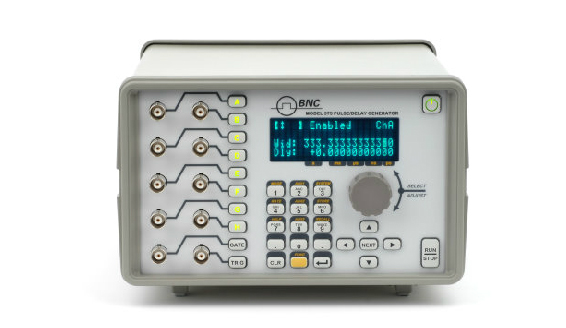
A flexible 2, 4, or 8-channel delay and pulse generator with 250 ps resolution and the deepest mix of electrical and optical I/O in the 500 series. One of the most versatile timing instruments available.
The Model 575 belongs to the Berkeley Nucleonics 500 series and delivers precision timing in a flexible, user-friendly form factor. It generates and synchronizes multiple pulses across a wide range of applications, with independent, digitally controlled delay and pulse width on every channel. That independence is what makes it suited to synchronizing complex events where each output must fire at its own moment.
What distinguishes the 575 is its I/O flexibility. The instrument ships in 2, 4, or 8-channel configurations, and those channels can mix electrical and optical inputs and outputs in almost any combination. A single eight-channel unit might carry an electrical input with four optical and four electrical outputs, or it can be ordered all-optical. Several high-voltage output modules extend the amplitude range, and the command set stays backwards compatible with earlier 500-series instruments.
With 250 ps resolution, rep rates to 10 MHz, and a cost structure aimed at laser triggering, particle image velocimetry, and laser-induced breakdown spectroscopy, the 575 is one of the most versatile delay generators on the market.
2Key Features
2, 4, or 8 independent output channels
250 ps resolution on delay and pulse width
Delay range 0 to 1000 s
Pulse width range 10 ns to 1000 s
Repetition rate up to 10 MHz
Accuracy of 1 ns + 0.0001 × setpoint
Modes for single and double pulse, burst, divide-by-N, duty cycle, and stored profiles
External clock synchronization and high-voltage output options
Configurable electrical and optical inputs and outputs
USB and RS-232 standard, with Ethernet and GPIB available
Backwards-compatible command set
New features
Illuminated channel enable buttons. Each channel has a designated enable/disable button that illuminates when the channel is active, for easy reference. A run/stop indicator on the front panel LCD and an illuminated run/stop button further simplify setup.
Selectable clock reference. Additional inputs and outputs for external clock syncing, specifiable from 10 MHz to 100 MHz. Sync with the mode-lock oscillator of a laser, or phase lock multiple units with one clock.
Flexible gating options. Gate with a channel or on any input, gate individual channels or gate all, and gate immediately (output inhibit) or after a pulse (pulse inhibit).
Individual rates. Each channel can run its own rate, referenced to T0 or to any other channel, similar to having a separate clock for each output.
Auto-save. The unit stores its setup configurations while powering down and recalls them automatically on power-up.
Dual input panel connectors. Two inputs for triggering or gating, electrical or optical, in any trigger/gate combination. Trigger #2 can disable a triggered pulse train.
Front panel optical. An LED output stage at the front panel for noisy environments or communications applications, configurable for 2, 4, or 8 outputs at 820 nm or 1300 nm.
Front panel high voltage. A front panel high-voltage option adjustable from 5 V to 35 V in 200 mV steps, on 2, 4, or all 8 channels.
Combined output types. Outputs are configured in modules and combined in pairs, so optical, standard electrical, and high-voltage electrical outputs can share one instrument. Custom or additional output modules can be added as the need arises.
Field programmability. Functions can be upgraded in the field, including custom feature upgrades, via a fully programmable FPGA.
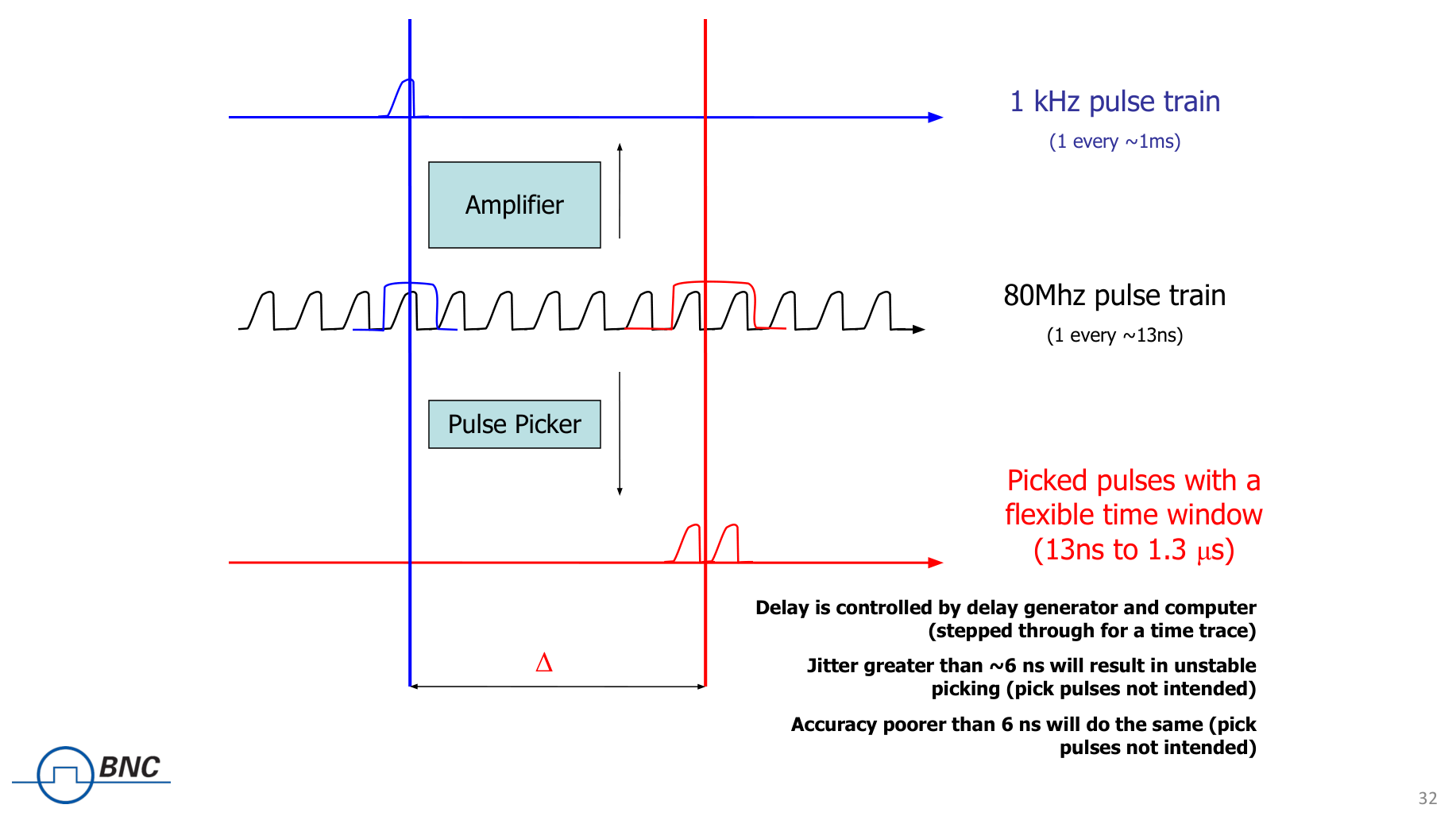
Pulse picking. Using an external modulation up to 100 MHz, select 1 out of every X pulses for a given channel.
Custom output modes. Custom modules such as the TZ-50 expand the capability set. The TZ-50 option allows a TTL signal into 50 ohms.
Negative delay. Reference one channel with respect to another in positive or negative time increments, synchronizing channels relative to each other by using one channel as another's trigger.
3Channels & Timing Architecture
The 575 builds its timing from an internal rate generator and a set of independent channels. The rate generator sets the master period, and each channel applies its own delay and width referenced to that period. Channels can be electrical or optical, and the mix is set at order time.
Internal rate generator
Parameter
Value
Rep rate
0.001 Hz to 10.000 MHz (1000 s to 100 ns)
Resolution
5 ns
Accuracy
Same as timebase
Jitter
50 ps
Setting
1 cycle
Burst mode
1 to 10,000,000
Optical fiber advantages
Optical I/O gives the 575 capabilities that copper cannot. Fiber is immune to electromagnetic interference, translates trigger levels between different electrical potentials, and produces no sparks or high-voltage transients in noisy environments. It is smaller and lighter than copper, spans longer distances without signal degradation, and reaches up to 1.5 km with standard transmitters and receivers. The optical channels work with 50/125, 62.5/125, 100/140, and 200 µm HCS fibers.
4Specifications
Quick specs
Parameter
Value
Outputs
2, 4, or 8 independent channel outputs
Pulse width
10 ns to 1000 s
Pulse delay
0 ns to 1000 s
Pulse and delay resolution
250 ps
Accuracy
1 ns + 0.0001 × setpoint
RMS jitter
200 ps
Timebase
25 ppm
Voltage input
60 V peak
Delays
Parameter
Value
Range
0-1000 s
Resolution
250 ps
Timebase
25 ppm
RMS jitter
200 ps
Pulse inhibit delay
120 ns
Output inhibit delay
50 ns
Electrical (TTL / adjustable) outputs, standard
Parameter
Value
Number of channels
2, 4, or 8 channel outputs
Impedance
50 Ω
Pulse width range (TTL)
10 ns to 1000 s
Rise time (TTL)
3 ns typ
Slew rate (adjustable)
0.1 V/ns
Overshoot
< 100 mV + 10% of pulse amplitude
Levels
TTL 0 to 4 VDC into high impedance. *VAR adjustable amplitude, 2.0 to 20.0 VDC with 10 mV res, 20.0 VDC max transition into high impedance
Electrical inputs
Parameter
Value
Number
0 or 2
Rate
DC to 1(0.2 us + longest delay)
Threshold
0.2 to 15 VDC
Max input voltage
60 V peak
Resolution
10 mV
Impedance
1 MΩ + 40 pF or 50 Ω
Function(s)
Individual channel trigger; gate/follower
Trigger slope
Rising or falling
Gate polarity
Active high or active low
Trigger jitter
< 2 ns
Optical inputs (Option IL82 or IL130)
Parameter
Value
Number
0 or 2
Wavelength
820 nm or 1300 nm
Max signal rate
5 Mbd
Max link distance
1.5 km
Connector type
ST
Resolution
500 ps
Accuracy
2 ns + 0.001 × delay
Optical trigger
2412
Trigger delay
< 300 ns
Jitter
< 15 ns
Optical outputs (Option L82 or L130)
Parameter
Value
Number
0, 2, 4, or 8
Wavelength
820 nm or 1300 nm
Max signal rate
5 MBd
Max link distance
1.5 km
Connector type
ST
Pulse width range
10 ns to 1000 s
Delay range
0 ns to 1000 s
Resolution
500 ps
Accuracy
1 ns + 0.0001 × delay
Standard features and functions
Feature
Specification
Communications
USB / RS-232
Global gates/triggers
2 global gate/trigger inputs
Channel gates/triggers
Optical/electrical available (5 ns jitter)
External clock in
10 MHz to 100 MHz, user selectable in discrete values
External clock out
10 MHz to 100 MHz, user selectable in discrete values
Command set compatibility
Backwards compatible
Physical and shipping
Parameter
Value
Shipping dimensions
18 × 12 × 9″
Shipping weight
10 lbs
Unit dimensions
Not published on source page (verify)
Unit weight
Not published on source page (verify)
Power
Not published on source page (verify)
5Triggering & I/O
The 575 provides standard external gate and trigger inputs alongside its outputs. The gate input inhibits pulses or outputs globally, with individual channel enables. The trigger input starts single pulses, bursts, or continuous streams.
External gate input (standard)
Parameter
Value
Number
0 or 1
Threshold
0.2 to 15 VDC
Max input voltage
60 V peak
Resolution
10 mV
Polarity
Active high / active low
Function
Pulse inhibit or output inhibit
Channel behavior
Global with individual channel enables
External trigger input (standard)
Parameter
Value
Number
1 or 2
Rate
DC to 1/(200 ns + longest delay), maximum of 5 MHz
Threshold
0.2 to 15 VDC
Max input voltage
60 V peak
Resolution
10 mV
Slope
Rising or falling
Impedance
1 MΩ + 40 pF or 50 Ω
Jitter
800 ps RMS
Insertion delay
180 ns max
6Options & Configurations
The 575 base models ship with AT20 electrical outputs. From there, the output modules and system options let you tailor amplitude, impedance, and communications to the application.
Output module options
Option
Description
AT20 (standard)
Selectable TTL or adjustable. TTL ~4 V into Hi-Z, 3 ns rise. Adjustable 2 to 20 V into Hi-Z (or 1 to 10 V into 50 Ω), slew 0.1 V/ns
TZ50
TTL ~4 V into 50 Ω, 3 ns rise. Adjustable 2 to 20 V into Hi-Z (or 1 to 10 V into 50 Ω), slew 0.1 V/ns
AT35
TTL ~4 V into Hi-Z, 3 ns rise. Adjustable 5 to 35 V into 50 Ω, 30 ns rise. Max rep rate reduced to 4 kHz
TZ35
Combination of TZ50 and AT35. TTL ~4 V into 50 Ω; adjustable 5 to 35 V into 50 Ω, 30 ns rise. Max rep rate reduced to 4 kHz
AT45
Selectable high/low Z. High: up to 45 V into Hi-Z, rise < 9 ns. Low: up to 45 V into 50 Ω, rise < 2 ns. Max rep rate reduced to 100 kHz. Maximum four AT45 channels per unit
Optical output options
Option
Description
L82
820 nm optical output, 5 MBd, 1.5 km max link, ST connector
L130
1300 nm optical output, 5 MBd, 1.5 km max link, ST connector
System options
Option code
Description
DT15
Dual trigger. Enables the gate input to act as a second trigger
COM
Extended communications. Adds Ethernet and GPIB
EU
Replaces the North American cord with a European cord
All base models include AT20 electrical outputs. Optical inputs and outputs are added through the IL82/IL130 and L82/L130 options described above.
7Applications
Imaging
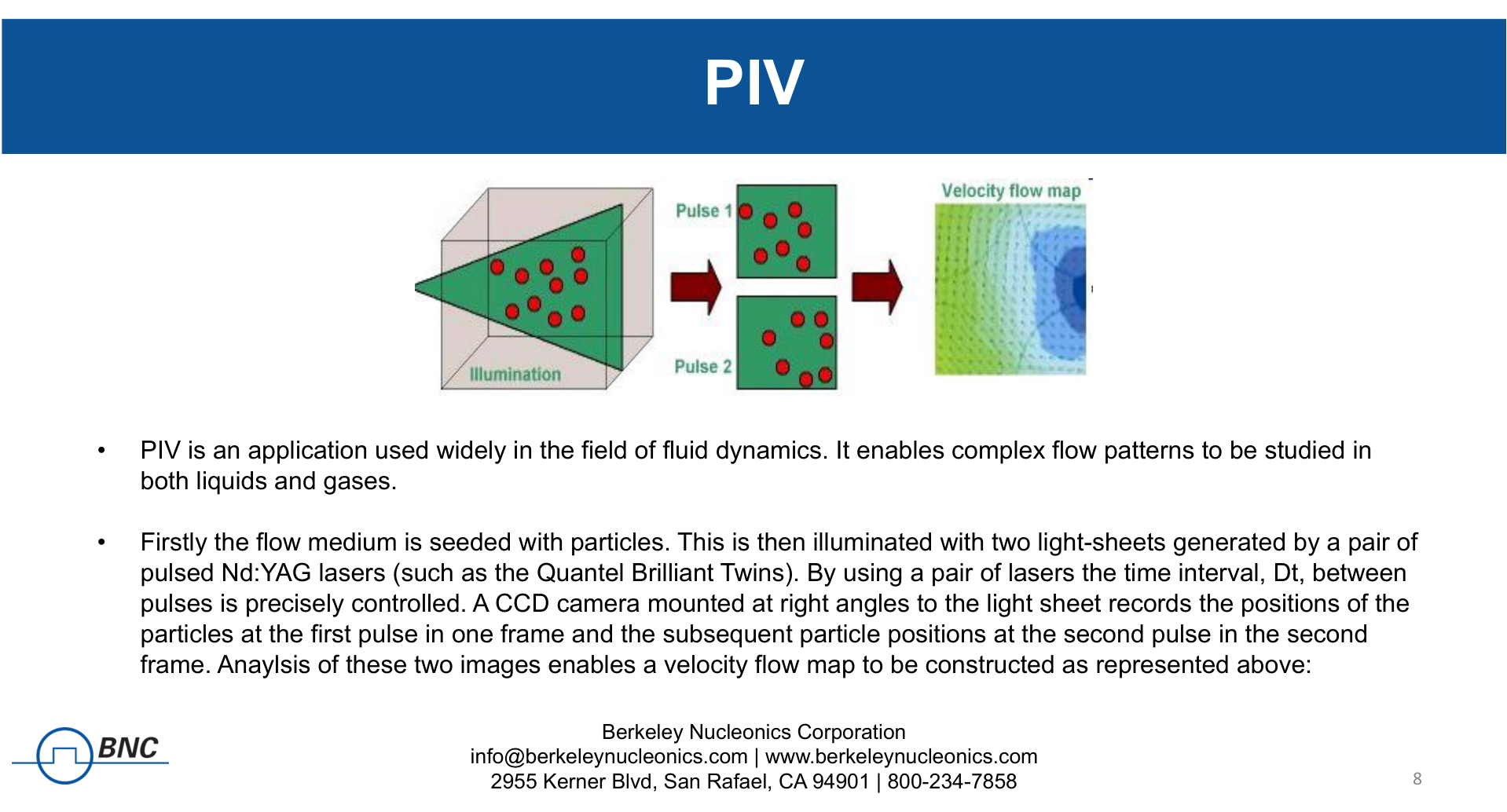
Fluid dynamics, including particle image velocimetry (PIV)
Laser-induced breakdown spectroscopy (LIBS)
Laser triggering and synchronization
Laser gating
The optical I/O makes the 575 a natural fit wherever triggers cross electrical potentials or travel through electrically noisy environments, including pulsed-power and high-voltage labs.
Pulse picking in practice. The delay generator selects individual pulses from a fast laser train into a flexible 13 ns to 1.3 microsecond window. Low jitter keeps the picked pulse the intended one.Particle image velocimetry. Paired light sheets fire a precise interval apart, and the delay generator sets that timing so the camera can resolve the flow into a velocity map.
8Ordering
Order the 575 by channel count, then add output modules, optical I/O, and system options to match the application. Start from a base variant and layer the options.
Step
Selection
1. Base model
575-2C, 575-4C, or 575-8C (includes AT20 electrical outputs)
2. Output modules
TZ50, AT35, TZ35, or AT45 as needed
3. Optical I/O
IL82/IL130 inputs, L82/L130 outputs
4. System options
DT15 dual trigger, COM (Ethernet + GPIB), EU cord
For a full ordering chart and a configuration review, contact Berkeley Nucleonics Corporation at info@berkeleynucleonics.com or 800-234-7858.
Verification notes. Unit dimensions, unit weight, and power draw are not published on the source product page (verify). Confirm all configuration details and values against the latest Model 575 datasheet and ordering chart before quoting.