1Description
The Model 525 Digital Delay/Pulse Generator offers users a performance benchtop delay generator rich with output features in a compact package. The interface is USB only, which eliminates the bulky front panel components and reduces the potential for mechanical problems. The timing and triggering flexibility is outstanding, with 20 MHz rep rates, 2 ns timing resolution, < 50 ps RMS Channel jitter and internal or external triggering options. Outputs can be selected for each channel, giving users the ability to trigger, gate or pulse various devices in a research project with different requirements. Single Pulse, Continuous, Burst, Duty Cycle and Cycle Counting are all selectable options for each channel. Wide pulses are also possible, with a width range of 10 ns – 1000 s and a delay from trigger range up to 1000 s. Trigger externally with signals up to 30 V peak and widths as low as 20 ns on the rising or falling edge.
The friendly BNC GUI will be familiar to existing customers, with a few new features added. The additional channels in the Model 525 allow for a greater variety of pulse sequences and multiplexing. SCPI and LabView compatibility offer users many options to interface to their Model 525.
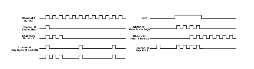
See Output Mode Timing Diagram in the Output Mode Timing section, which illustrates some popular output modes (Normal, Single Shot, Burst, Duty Cycle, Gate, Wait, and Multiplex).
2Features & Applications
Features
- 6 Channels of Delay and Width
- 2 ns Timing Resolution
- < 50 ps RMS Channel Jitter
- USB Power
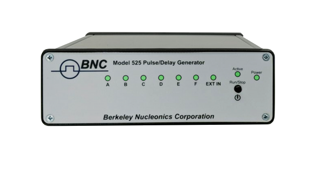
- LED Indicators
Applications
- ICCD/PIV Testing
- Laser Triggering / Gating
- Pulse DUTs and Pump Lasers
- Radar / Sonar Simulation
- High Speed Photography
3Output Modes & GUI
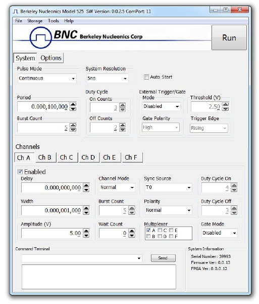
The provided GUI gives full control of the Model 525. The main BNC GUI interface offers:
- System Wide Trigger Selection (Internal or External)
- Flexible Triggering Options (Leading or Falling Edge, etc.)
- Channel Specific Menu offering unprecedented flexibility (Polarity, Multiplex, etc.)
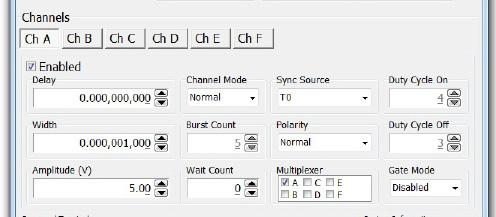
The Channel Parameter Sub-Menu lets users select channel properties quickly for absolute flexibility in output sequences (independent time and amplitude domain, burst, multiplex, gating, etc.).
4Rear Panel & Operation
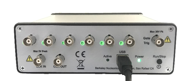
The handy rear panel offers ample spacing of output connectors for easy setup. The Output nomenclature is backlit to enable a visual indicator of active channels. An external trigger can be used to initiate pulses, or a gate pulse can be used to limit pulses according to an active high or active low gate. Use the clock in to synchronize to laser cavities or other external sources. The compact design and power over USB reduce the bench / rack space required.
With illuminated indicators on both panels, the Model 525 can be positioned with output cables on the front or back depending on user requirements. The Power Button doubles as a run/stop control as well, simply press to run or hold to power down.
5Internal Rate Generator
| Parameter | Specification |
|---|---|
| Rate (To Period) | 0.001Hz to 20MHz (1000s to 50ns) |
| Resolution & Accuracy | 4 ns |
| Jitter | < 50 ps RMS |
| Burst / Duty Cycle Mode | 1 to 1,000,000 pulses |
| Timebase | 200 MHz / 250MHz low jitter PLL |
| Oscillator | 50 MHz, 50 ppm crystal oscillator, optional 1ppm clock |
| Pulse Control Modes | Internal rate generator, external trigger / gate |
| System Output Modes | Single, continuous, burst, duty cycle, cycle counts |
| Pulse & Period Counter | 32 Bit |
| Synchronized Update Mode | Updates widths and delays on command |
6Pulse / Delay Generation
| Parameter | Specification |
|---|---|
| Width / Delay Resolution | 4 ns |
| Width Range | 10 ns - 1000 s |
| Width Accuracy | 10 ns + 0.0001 x (width + delay) |
| Delay Range | ±1000 s |
| Delay Accuracy | 4 ns / 5 ns + (0.0001 x delay) |
| Multiplexer | Any / all channels may be OR'd to any / All outputs. 2x the number of outputs via virtual channels for mixing |
| Channel Output Modes | Single Shot, normal, burst, duty cycle |
| Channel Control Modes | Internally triggered or externally gated. Each channel may be independently set to any of the modes. |
| Jitter (Channel to Channel) | < 250 ps RMS |
7External Gate / Trigger Input
| Parameter | Specification |
|---|---|
| Threshold | 0.2 to 15 VDC |
| Max Input Voltage | 30 V Peak |
| Gate Polarity | Active high / active low |
| Gate Control Modes | Pulse inhibit / output inhibit |
| Trigger Edge | Rising or falling |
| Trigger Rate | DC to 20 MHz |
| Trigger Input Jitter | < 5 ns RMS |
| Trigger Minimum Pulse Width | 20 ns |
| Trigger Insertion Delay | < 100 ns |
| Pulse Inhibit Delay | < 150 ns |
| Output Inhibit Delay | < 100 ns |
| Trigger Input Function | System can generate a single, burst or duty cycle response of pulses for every external trigger pulse. |
8Outputs
| Parameter | Specification |
|---|---|
| Output Impedance | 50 ohm |
| Output Level | 3.3 – 5 VDC into ≥ 1 K ohm, 1.7 – 2.5 VDC into 50 ohm |
| Resolution | 20 mV |
| Current | 5 mA into 1 K ohm, 50 mA into 50 ohm |
| Rise Time | < 2ns @ 5 V (high impedance), < 1ns @ 2.5 V (50 ohm) |
| Overshoot | < 100 mV + 10 % of pulse amplitude |
9General
| Parameter | Specification |
|---|---|
| USB | Standard USB 2.0 |
| Baud Rate | Up to 115200 bits /sec typ. |
| Voltage | + 5 VDC ± 250 mVDC |
| Current | < 470 mA |
| Dimensions | 7.125 x 5.1 x 1.5 inches (18.1 x 13 x 3.8 cm). 1lb |
10Output Mode Timing Diagram
The diagram below illustrates some popular output modes available per channel: Normal, Single Shot, Burst, Duty Cycle, Gate (active high), Wait, and Multiplex.
11Ordering Information
| Model | Description |
|---|---|
| Model 525 | 6 Channel Digital Delay / Pulse Generator (includes travel bag) |