1Overview
The Model 507 and Model 508 are high current pulse generators from the Directed Energy Division of Berkeley Nucleonics. Both act as firesets for high-energy initiator testing, delivering controlled current pulses into low-impedance loads such as airbag squibs, detonators, and pyrotechnic igniters. They cover different ranges of current, pulse width, repetition rate, and compliance voltage, so this page presents each model against its own datasheet.
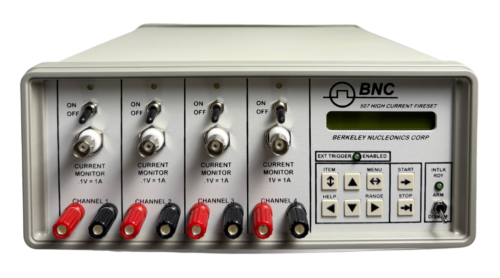
The Model 507 is the high-current unit. It produces adjustable current signals up to 25 A per channel from a 44 V minimum bank voltage, with pulse widths from 100 µs to 100 ms and delays to just under 100 seconds, in 200 ns steps. It ships in a benchtop chassis with 2 or 4 independent channels and a TTL Sync output referenced to T0.
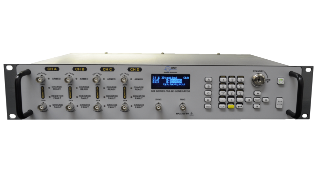
The Model 508 is the precision, fast-edge unit. It delivers 0.10 to 6 A per channel into a 19 to 22 V compliance with sharp edges (about 550 ns resistive rise time at 6 A) and adds integrated 4-wire resistance measurement, current and voltage monitors, and statistical firing modes. It ships in a 19-inch 2U rackmount chassis with 2 or 4 channels.
Both pulsers ship from the same San Rafael, California build with one support path.
2How They Work
Both models are current sources rather than voltage sources. Each regulates current into the load and takes its pulse timing from an internal rate generator or an external trigger, with every channel holding its own independent delay and pulse width.
The Model 507 favors wide, high-slew current pulses into a higher 44 V compliance, which suits slowly repeated, large-charge firing. Timing comes from a 5 MHz, 25 PPM crystal oscillator, with delay and pulse width set in 200 ns steps and 100 ns RMS jitter. Each output drives 0 to 25 A into loads from roughly 1 to 10 ohm, with a slew rate above 2.5 A/µs.
The Model 508 favors faster, lower-voltage pulses across a broad span of repetition rates. Its internal rate generator spans 0.01 Hz to 40 kHz with 10 ns RMS jitter and supports single-pulse and burst output of 2 to 250 pulses. Isolated current and voltage monitor outputs let the operator capture the delivered pulse on an oscilloscope, and integrated 4-wire resistance measurement characterizes the bridge wire before and after firing.
3Model 507 vs 508
The two models trade current for speed and measurement. The table below is the at-a-glance comparison; the verbatim datasheet specifications for each model follow in their own sections.
| Parameter | Model 507 | Model 508 |
|---|---|---|
| Current per channel | 0 to 25 A | 0.10 to 6 A |
| Compliance / bank voltage | 44 V minimum bank voltage | 19 to 22 V |
| Pulse width | 100 µs to 100 ms* | 5 µs to 100 s* (amplitude limited) |
| Delay range | 0 to 99.9999998 s | 0 to 30 s |
| Timing resolution | 200 ns | 100 ns |
| RMS jitter | 100 ns | 10 ns |
| Rep / rate generator | DC to 1/(75 ms + largest delay + period) | 0.01 Hz to 40 kHz |
| Resistance measurement | — | 0.1 to 150 ohm, 4-wire |
| Channels | 2 or 4 independent | 2 or 4 independent |
| Form factor | Benchtop | 19 in, 2U rackmount |
| Communications | RS232 (GPIB optional) | USB, RS232 (Ethernet optional) |
*Model 507: contact us for other options for amperage and pulse widths. Model 508: maximum pulse width is limited by current amplitude (1 A can go up to 100 s, 6 A is limited to 300 ms).
4Model 507 Specifications
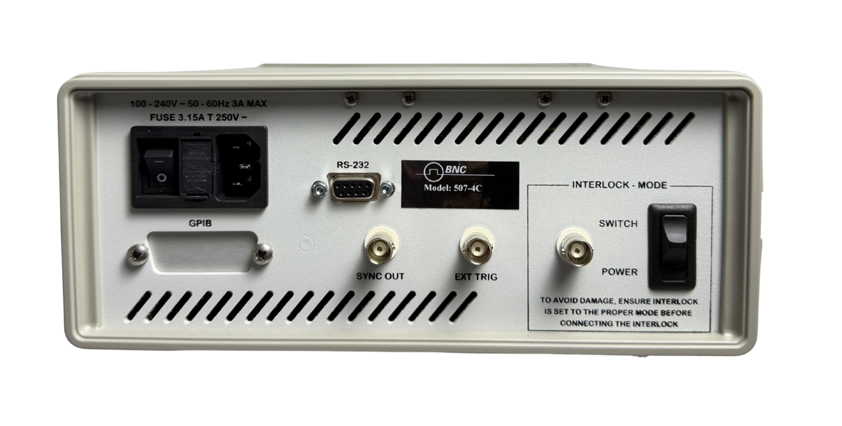
The Model 507 ships in a 2-channel (507-2C) or 4-channel (507-4C) configuration, each output digitally controlled and independent. The following values are taken from the Model 507 datasheet.
| Parameter | Specification |
|---|---|
| Models | 507-2C (2 independent channel outputs); 507-4C (4 independent channel outputs) |
| Channels | Independent outputs, digitally controlled delay and pulse width |
| Current output | 0 to 25 A* (44 V minimum bank voltage) |
| Current resolution | 10 mA |
| Current accuracy | 50 mA |
| Delay | 0 to 99.9999998 s |
| Delay resolution | 200 ns |
| Pulse width | 100 µs to 100 ms* |
| Pulse width resolution | 200 ns |
| Accuracy | 100 ns + .0001 x delay |
| Timebase | 5 MHz, 25 PPM crystal oscillator |
| RMS jitter | 100 ns |
| Trigger delay | ext trig to T0, 10 µs |
| External trigger rate | DC to 1/(75 ms + largest delay + period) |
| External trigger threshold | 3 VDC (3 mA into optoisolator) |
| External trigger impedance | 1000 Ω |
| Internal rate generator modes | Single shot, external trigger |
| Internal rate generator RMS jitter | 100 ns |
| Output impedance (T1, T2) | 1.405 Ω |
| Output slew rate | > 2.5 A/µs |
| Output overshoot | < 100 mA + 10% of pulse amplitude |
| Output amplitude | 0 to 25 A (loads 1 to 10 ohm) |
| Peak current | 25 A per channel |
| DC current limit | 150 mA (each channel) |
| Standard communications | RS232 |
| Memory storage | 12 slots |
| Weight | 10 lbs. |
| Power | < 100 W @ 120 or 220 VAC |
| Options | G – GPIB Interface |
*Contact us for other options for amperage and pulse widths.
5Model 508 Specifications
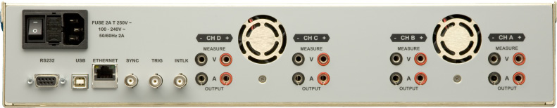
The Model 508 ships as the 508-2C or 508-4C in a 19-inch 2U chassis with current sensing and resistance measurement. The following values are taken from the Model 508 datasheet.
| Parameter | Specification |
|---|---|
| Configurations | 508-2C (2 output channels); 508-4C (4 output channels); input module front and rear trigger |
| Output amplitude | 0.10 to 6 A; 2 mA resolution; +/- 0.5% to 2% accuracy |
| Compliance voltage level | 19 to 22 Volts |
| Pulse width range | 5 µs to 100 s*; +/- 0.1% error; 100 ns resolution |
| Delay range | 0 to 30 s; +/- 0.1% error |
| Rise time, rising edge (inductive) | 4 µs (1 ohm, 50' cable, 6 A), varies with load |
| Rise time, rising edge (resistive) | 550 ns (1 ohm, 2" cable, 6 A), varies with load |
| Slew rate, rising edge (inductive) | 2 A/µs @ 6 A; 1 A/µs @ 3 A; 0.30 A/µs @ 1 A (1 ohm and 50' cable); varies with load |
| Slew rate, falling edge (inductive) | -1.60 A/µs @ 6 A; -0.90 A/µs @ 3 A; -0.30 A/µs @ 1 A (1 ohm and 50' cable); varies with load |
| Slew rate, rising edge (resistive) | 6.3 A/µs @ 6 A; 9.5 A/µs @ 3 A; 2.2 A/µs @ 1 A (1 ohm and 2" cable); varies with load |
| Slew rate, falling edge (resistive) | -5.2 A/µs @ 6 A; -4.0 A/µs @ 3 A; -1.3 A/µs @ 1 A (1 ohm and 2" cable); varies with load |
| Internal rate generator | 0.01 Hz to 40 KHz; 100 ns resolution; 20 ns accuracy; 10 ns RMS jitter |
| Burst mode | 2 to 250 pulses |
| Output modes | Single pulse, burst |
| Control modes | Internal rate generator, external trigger |
| External trigger function | Generate individual pulses (single shot or burst) |
| External trigger front or rear | Selectable between front or rear panel inputs |
| External trigger rate | Min = 5 X longest pulse width; Max = 200 seconds |
| Insertion delay | 300 ns |
| External trigger jitter | 10 ns |
| External trigger impedance | 1K Ω |
| Slope | Rising or falling |
| Trigger filter | Filters out unwanted “glitch” or “runt” pulses; range 0.02 µs to 1 ms; 0.02 µs resolution |
| Trigger level | 2 to 15 V; 100 mV level threshold |
| Voltage monitor (isolated) | 0.2 V/V; <4% error |
| Current monitor (isolated) | 0.5 V/A; <4% error |
| Monitor bandwidth | Min = 100 kHz; Max = 1000 kHz |
| Resistance measurement range | 0.1 to 150 Ohms; .01 Ohms resolution |
| Resistance measurement error | < 4% (.5 to 15 Ohms); <10% (16 to 150 Ohms) |
| Resistance measurement current | 100 mA max. |
| Sync outputs | Front and rear; T0, channels A through D |
| Standard communications | USB (serial bridge); RS232 (115200, 57600, 38400, 19200, 9600, 4800 baud) |
| Size | 9" 2U x 10" 2U size rack mount |
| Electrical | 100-240 V, 50-60 Hz |
| Safety, remote interlock | Shorting interlock |
| Safety, arming key switch | Removable keyswitch |
| Safety, internal error checking | Checks control circuit for errors |
| Options | E – Ethernet |
*Maximum pulse width is limited by current amplitude. 1 A can go up to 100 s and 6 A is limited to 300 ms.
6Triggering & Safety
Both models take pulse timing from an internal rate generator or an external trigger. The Model 507 uses a 3 VDC trigger threshold (3 mA into an optoisolator) on a 1000 ohm input, keeping the trigger path isolated from the high current output stage, with a 10 µs external-trigger-to-T0 delay and a built-in safety interlock. A TTL Sync output referenced to T0 serves as a reference for cameras and instrumentation, and 12 memory slots hold complete setups.
The Model 508 triggers from selectable front or rear inputs at a 2 to 15 V level on a 1 kohm input, with rising or falling slope, a 100 mV level threshold, a trigger filter that rejects glitch and runt pulses, 300 ns insertion delay, and 10 ns jitter. Safety is layered: a removable keyed front-panel fire enable, mechanical and software interlocks, a remote shorting interlock, and internal error checking that verifies the control circuit. The 508 fires single pulses or bursts of 2 to 250 pulses and provides front and rear sync outputs (T0, channels A through D).
7Applications
The Model 507 and Model 508 suit firing and characterization of low-impedance, high-energy initiators where a specific current, pulse-width, and repetition-rate range is needed:
- Airbag deployment testing, squib detonation
- Detonator and pyrotechnic initiator testing
- Igniter triggering
- Explosive testing and ballistics work
- Model 507. High current firing to 25 A into a 44 V compliance for large-charge initiators
- Model 508. Precision 0.10 to 6 A firing with 4-wire bridge-wire resistance measurement, plus statistical sensitivity testing (Bruceton, Neyer)
8Ordering Information
| Part number | Description |
|---|---|
| 507-2C | Model 507 High Current Pulse Generator, two independent 25 A outputs, benchtop |
| 507-4C | Model 507 High Current Pulse Generator, four independent 25 A outputs, benchtop |
| 507 option G | GPIB Interface |
| 508-2C | Model 508 Current Pulse Generator, two independent 6 A channels, 2U rackmount |
| 508-4C | Model 508 Current Pulse Generator, four independent 6 A channels, 2U rackmount |
| 508 option E | Ethernet; adds Ethernet to the standard USB and RS232 interfaces |
Contact
For a quote, configuration help, or application support, reach the Berkeley Nucleonics team.
Email: info@berkeleynucleonics.com
Phone: 800-234-7858